 VG
VG
for k=0,1,2,...,7

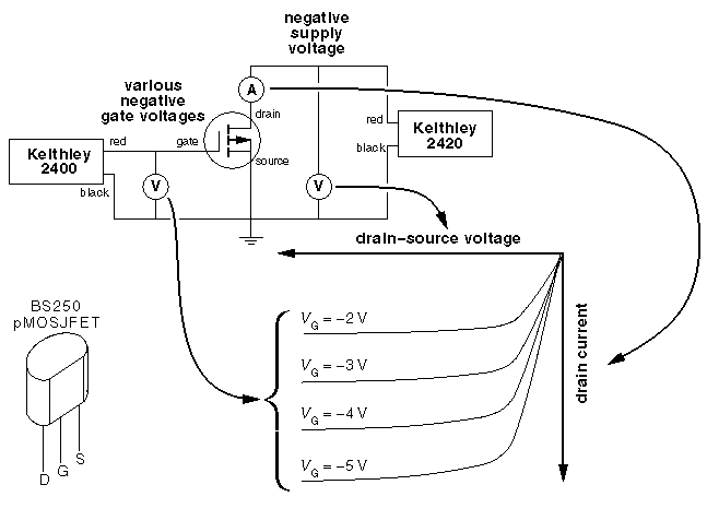
As shown in the above circuit, the Keithley 2420 powers the FET's drain; the Keithley 2400 powers the FET's gate. (The volt and amp meters shown are actually internal to the Keithley source-meters. The only things needed for this characteristic curve plot are the two Keithley source-meters, your pMOSFET, and the connecting wires.) Connect up this circuit, decide on the test ranges (the defaults are fine for a BS250) and hit "Test It". The data will be collected under computer control. Data collection will take about a minute...don't get impatient! You should almost immediately see the source-meters kick into action. The following screen will allow you to print a copy of the plotted data, view the plot as a PostScript or pdf file, and/or view the actual numbers collected.
A total of eight IV curves will be generated:
VG = VG0 + k  VG
VG
for k=0,1,2,...,7
If you are unsure of the meaning of these test ranges, click here.